| Overview |
| Nature of Wind |
| Method 2 Provisions |
| Example Problems |
|
References |
| Report Errors or Make Suggestions |
Section 7.4.1
Example Problem 7.1
Two Story Building
Method 2
Last Revised: 11/04/2014
Given: The enclosed office building shown in Figure 7.4.1.1. The building is located in a region with a wind speed (3-sec gust) of 120 mph. The exposure is Exposure C. The building is on flat terrain.
Figure 7.4.1.1
Building Definition
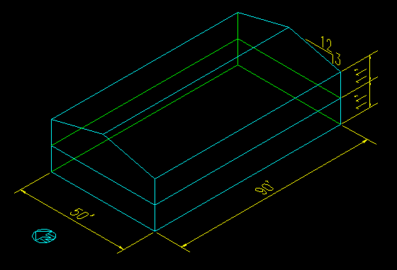
Wanted: The wind pressures applied to the surfaces and the net forces applied to the building.
Solution: To solve this problem, we need to independently look at two different wind directions, but first we will define a few parameters.
Determine critical elevations:
- Mean Roof Height: h = 2*11' + (3/12)*25'/2 = 25.1 ft
- Mean 2nd Floor Height: h = 11' + 11'/2 = 16.5 ft
- Mean 1st Floor Height: h = 11'/2 = 5.5 ft
Compute the Velocity Pressures, qz = .00256 Kz Kzt Kd V2 I (ASCE 7-05 Equation 6-15)
- Kzt = 1 (Flat Terrain)
- Kd = .85 (ASCE 7-05 Table 6-4, Buildings)
- I = 1.0 (ASCE 7-05 Table 6-1, Category II building)
- Kz = varies with elevation = 2.01(max(h,15)/900)(2/9.5), (ASCE 7-05 Tables 6-2 and 6-3)
| h | Kz | qz | |
| (ft) | (psf) | ||
| Roof | 25.125 | 0.946 | 29.7 |
| 2nd flr | 16.5 | 0.866 | 27.1 |
| 1st flr | 5.5 | 0.849 | 26.6 |
Compute the Internal Pressures, qhGCpi:
- GCpi = + 0.18 (ASCE 7-05 Figure 6-5)
- qh = 29.7 psf
- qhGCpi = + 5.34 psf
Determine the Gust Factor, G
- G = 0.85 (ASCE 7-05, 6.5.8.1)
Wind in the N/S Direction:
For this part of the problem we need to determine pressure coefficients for the locations shown in Figure 7.4.1.2 as well as for the side walls. These coefficients are then combined with the gust factor and velocity pressures to obtain the external pressures in each region.
Figure 7.4.1.2
N/S Building Section
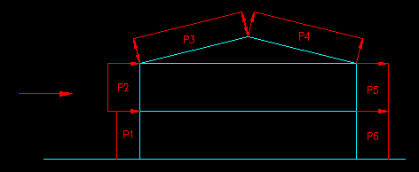
The pressure coefficients for the walls are found in ASCE 7-05 Figure 6-6 (pg 49)
For the Windward wall (P1 & P2), Cp is 0.8 for all elevations.
For the Leeward wall (P5 & P6), Cp is dependent on the ration of L/B. In this case L/B = 50'/90' = 0.556, so Cp = -0.50 for all elevations.
For the sidewalls (not shown in Figure 7.4.1.2), the value of Cp is -0.7 in all cases.
For the roof, the slope angle is 14.0 degrees. This is close to 15 degrees and probably not worth interpolating between the values given in ASCE 7-05 Figure 6-6. We also need to know that h/L = 25.1'/50' = 0.50. From the Figure we get that the values of Cp for the Windward side of the roof is -0.70 and -0.18. These values represent two different load cases. For the Leeward side, Cp is -0.50.
We can now compute the external pressures, qGCp, for each surface. The following table shows the computation results:
| Pressure | Cp | q | qGCp | |
| (psf) | (psf) | |||
| Windward Wall | P1 | 0.8 | 26.6 | 18.1 |
| P2 | 0.8 | 27.1 | 18.5 | |
| Windward Roof | P3 | -0.7 | 29.7 | -17.6 |
| P3 | -0.18 | 29.7 | -4.5 | |
| Leeward Roof | P4 | -0.5 | 29.7 | -12.6 |
| Leeward Wall | P5 | -0.5 | 29.7 | -12.6 |
| P6 | -0.5 | 29.7 | -12.6 | |
| Side Walls | P7 | -0.7 | 29.7 | -17.6 |
Combining with the internal pressures you get the following four load cases where:
- Case I includes the maximum windward pressure (-17.6 psf) and positive internal pressure
- Case II includes the minimum windward pressure (-4.5 psf) and positive internal pressure
- Case III includes the maximum windward pressure (-17.6 psf) and negative internal pressure
- Case IV includes the minimum windward pressure (-4.5 psf) and negative internal pressure
The net forces are found by multiplying the appropriate pressures by the areas over which they act. In this building all but the gable ends are rectangles, making the area calculation easier. Note that we are computing actual surface areas (as opposed to projected areas) in each of the cases below. Also, the sign is important. Negative signs indicate a force that is outward from the surface and a positive sign is inward. All forces are normal to their respective surfaces.
| Net Pressures: | Net Force | |||||||||
| Pressure | Case I | Case II | Case III | Case IV | Areas | Case I | Case II | Case III | Case IV | |
| (psf) | (psf) | (psf) | (psf) | (ft2) | (k) | (k) | (k) | (k) | ||
| Windward Wall | P1 | 12.8 | 12.8 | 23.4 | 23.4 | 990 | 12.62 | 12.62 | 23.19 | 23.19 |
| P2 | 13.1 | 13.1 | 23.8 | 23.8 | 990 | 12.99 | 12.99 | 23.55 | 23.55 | |
| Windward Roof | P3 | -23.0 | -9.9 | -12.3 | 0.8 | 2319 | -53.29 | -22.90 | -28.54 | 1.86 |
| Leeward Roof | P4 | -17.9 | -17.9 | -7.3 | -7.3 | 2319 | -41.60 | -41.60 | -16.85 | -16.85 |
| Leeward Wall | P5 | -17.9 | -17.9 | -7.3 | -7.3 | 990 | -17.76 | -17.76 | -7.19 | -7.19 |
| P6 | -17.9 | -17.9 | -7.3 | -7.3 | 990 | -17.76 | -17.76 | -7.19 | -7.19 | |
| Side Walls | P7 | -23.0 | -23.0 | -12.3 | -12.3 | 1413 | -32.46 | -32.46 | -17.38 | -17.38 |
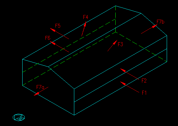
It is often useful to resolve each force into it's global components so that they can be easily added vectorially. Figure 7.4.1.3 shows the location of each of the resulting forces.
Figure 7.4.1.3
Building Forces for N/S Wind
| Case I | Case II | Case III | Case IV | ||||||||||
| Force | E/W | N/S | vert. | E/W | N/S | vert. | E/W | N/S | vert. | E/W | N/S | vert. | |
| (k) | (k) | (k) | (k) | (k) | (k) | (k) | (k) | (k) | (k) | (k) | (k) | ||
| Windward Wall | F1 | 0.00 | 12.62 | 0.00 | 0.00 | 12.62 | 0.00 | 0.00 | 23.19 | 0.00 | 0.00 | 23.19 | 0.00 |
| F2 | 0.00 | 12.99 | 0.00 | 0.00 | 12.99 | 0.00 | 0.00 | 23.55 | 0.00 | 0.00 | 23.55 | 0.00 | |
| Windward Roof | F3 | 0.00 | -12.93 | 51.70 | 0.00 | -5.55 | 22.22 | 0.00 | -6.92 | 27.69 | 0.00 | 0.45 | -1.80 |
| Leeward Roof | F4 | 0.00 | 10.09 | 40.36 | 0.00 | 10.09 | 40.36 | 0.00 | 4.09 | 16.34 | 0.00 | 4.09 | 16.34 |
| Leeward Wall | F5 | 0.00 | 17.76 | 0.00 | 0.00 | 17.76 | 0.00 | 0.00 | 7.19 | 0.00 | 0.00 | 7.19 | 0.00 |
| F6 | 0.00 | 17.76 | 0.00 | 0.00 | 17.76 | 0.00 | 0.00 | 7.19 | 0.00 | 0.00 | 7.19 | 0.00 | |
| Side Walls | F7a | -32.46 | 0.00 | 0.00 | -32.46 | 0.00 | 0.00 | -17.38 | 0.00 | 0.00 | -17.38 | 0.00 | 0.00 |
| F7b | 32.46 | 0.00 | 0.00 | 32.46 | 0.00 | 0.00 | 17.38 | 0.00 | 0.00 | 17.38 | 0.00 | 0.00 | |
| Sum | 0.00 | 58.29 | 92.06 | 0.00 | 65.66 | 62.58 | 0.00 | 58.29 | 44.03 | 0.00 | 65.66 | 14.54 |
Note that the maximum uplift and maximum horizontal force do not occur in the same load cases! Do not combined the two cases, design for each individually.
You will also notice that the internal pressure has no effect on the net horizontal force.
The net force in the lateral direction is zero since the forces on the side walls will cancel each other.
Wind in the E/W Direction
Figure 7.4.1.4 defines the pressures (with the exception of the lateral/side wall pressures) that need to be computed for wind loading from the E/W direction. In this case we combined all the leeward wall segments into one because they all have the same pressures.
Figure 7.4.1.4
E/W Building Section
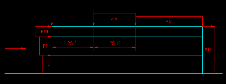
The pressure coefficients are taken from ASCE 7-05 Figure 6-6. Note that the coefficient for the leeward wall is obtained by interpolation with an L/B ratio of 1.8.
| Pressure | Cp | q | qGCp | |
| (psf) | (psf) | |||
| Windward Wall | P8 | 0.8 | 26.6 | 18.1 |
| P9 | 0.8 | 27.1 | 18.5 | |
| P10 | 0.8 | 29.7 | 20.2 | |
| Roof | P11 | -0.9 | 29.7 | -22.7 |
| P11 | -0.18 | 29.7 | -4.5 | |
| P12 | -0.5 | 29.7 | -12.6 | |
| P12 | -0.18 | 29.7 | -4.5 | |
| P13 | -0.3 | 29.7 | -7.6 | |
| P13 | -0.18 | 29.7 | -4.5 | |
| Leeward Wall | P14 | -0.34 | 29.7 | -8.6 |
| Side Walls | P15 | -0.7 | 29.7 | -17.6 |
Note that some of the pressures are applied to differently oriented surfaces. When the same pressure is applied to a different surface, we have chosen to label on as "a" and the other as "b". See Figure 7.4.1.5 for force applications. Four cases are computed, based on combinations of maximum/minimum roof pressures and + internal pressures.
Figure 7.4.1.5
Building Forces for E/W Wind
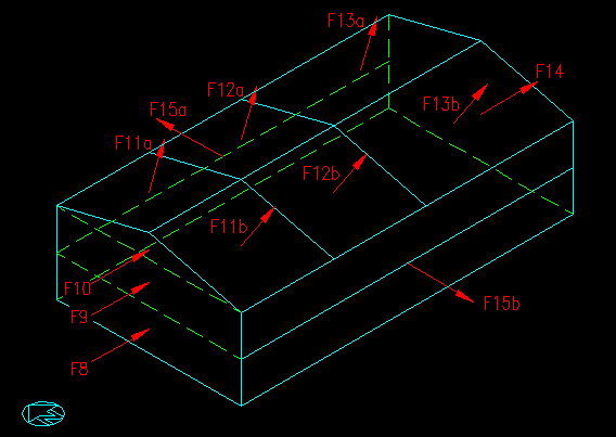
The net forces on each surface, in terms of direction relative the surface, are as follows:
| Pressure | Case I | Case II | Case III | Case IV | Area | Case I | Case II | Case III | Case IV | |
| (psf) | (psf) | (psf) | (psf) | (ft2) | (k) | (k) | (k) | (k) | ||
| Windward Wall | P8 | 12.8 | 12.8 | 23.4 | 23.4 | 550 | 7.01 | 7.01 | 12.88 | 12.88 |
| P9 | 13.1 | 13.1 | 23.8 | 23.8 | 550 | 7.21 | 7.21 | 13.09 | 13.09 | |
| P10 | 14.8 | 14.8 | 25.5 | 25.5 | 156 | 2.32 | 2.32 | 3.98 | 3.98 | |
| Roof | P11a | -28.0 | -9.9 | -17.3 | 0.8 | 647 | -18.12 | -6.39 | -11.22 | 0.52 |
| P11b | -28.0 | -9.9 | -17.3 | 0.8 | 647 | -18.12 | -6.39 | -11.22 | 0.52 | |
| P12a | -17.9 | -9.9 | -7.3 | 0.8 | 647 | -11.60 | -6.39 | -4.70 | 0.52 | |
| P12b | -17.9 | -9.9 | -7.3 | 0.8 | 647 | -11.60 | -6.39 | -4.70 | 0.52 | |
| P13a | -12.9 | -9.9 | -2.2 | 0.8 | 1026 | -13.23 | -10.13 | -2.28 | 0.82 | |
| P13b | -12.9 | -9.9 | -2.2 | 0.8 | 1026 | -13.23 | -10.13 | -2.28 | 0.82 | |
| Leeward Wall | P14 | -13.9 | -13.9 | -3.2 | -3.2 | 1256 | -17.47 | -17.47 | -4.06 | -4.06 |
| Side Walls | P15a | -23.0 | -23.0 | -12.3 | -12.3 | 1980 | -45.50 | -45.50 | -24.36 | -24.36 |
| P15b | -23.0 | -23.0 | -12.3 | -12.3 | 1980 | -45.50 | -45.50 | -24.36 | -24.36 |
Restating the forces in terms of the global coordinate system we get:
| Case I | Case II | Case III | Case IV | ||||||||||
| Pressure | E/W | N/S | vert. | E/W | N/S | vert. | E/W | N/S | vert. | E/W | N/S | vert. | |
| (k) | (k) | (k) | (k) | (k) | (k) | (k) | (k) | (k) | (k) | (k) | (k) | ||
| Windward Wall | F8 | 7.01 | 0.00 | 0.00 | 7.01 | 0.00 | 0.00 | 12.88 | 0.00 | 0.00 | 12.88 | 0.00 | 0.00 |
| F9 | 7.21 | 0.00 | 0.00 | 7.21 | 0.00 | 0.00 | 13.09 | 0.00 | 0.00 | 13.09 | 0.00 | 0.00 | |
| F10 | 2.32 | 0.00 | 0.00 | 2.32 | 0.00 | 0.00 | 3.98 | 0.00 | 0.00 | 3.98 | 0.00 | 0.00 | |
| Roof | F11a | 0.00 | 4.40 | 17.58 | 0.00 | 1.55 | 6.20 | 0.00 | 2.72 | 10.88 | 0.00 | -0.13 | -0.50 |
| F11b | 0.00 | -4.40 | 17.58 | 0.00 | -1.55 | 6.20 | 0.00 | -2.72 | 10.88 | 0.00 | 0.13 | -0.50 | |
| F12a | 0.00 | 2.81 | 11.26 | 0.00 | 1.55 | 6.20 | 0.00 | 1.14 | 4.56 | 0.00 | -0.13 | -0.50 | |
| F12b | 0.00 | -2.81 | 11.26 | 0.00 | -1.55 | 6.20 | 0.00 | -1.14 | 4.56 | 0.00 | 0.13 | -0.50 | |
| F13a | 0.00 | 3.21 | 12.83 | 0.00 | 2.46 | 9.82 | 0.00 | 0.55 | 2.21 | 0.00 | -0.20 | -0.80 | |
| F13b | 0.00 | -3.21 | 12.83 | 0.00 | -2.46 | 9.82 | 0.00 | -0.55 | 2.21 | 0.00 | 0.20 | -0.80 | |
| Leeward Wall | F14 | 17.47 | 0.00 | 0.00 | 17.47 | 0.00 | 0.00 | 4.06 | 0.00 | 0.00 | 4.06 | 0.00 | 0.00 |
| Side Walls | F15a | 0.00 | 45.50 | 0.00 | 0.00 | 45.50 | 0.00 | 0.00 | 24.36 | 0.00 | 0.00 | 24.36 | 0.00 |
| F15b | 0.00 | -45.50 | 0.00 | 0.00 | -45.50 | 0.00 | 0.00 | -24.36 | 0.00 | 0.00 | -24.36 | 0.00 | |
| Sum | 34.01 | 0.00 | 83.34 | 34.01 | 0.00 | 44.43 | 34.01 | 0.00 | 35.31 | 34.01 | 0.00 | -3.60 |