| Overview |
| Comparing LRFD & ASD Results |
|
References |
| Report Errors or Make Suggestions |
BGASCE7-10 Section 2.5
Homework Problems
Last Revised: 11/04/2014
For all these problems, submit your work in a single Microsoft EXCEL file unless otherwise approved by your instructor.
Problem 2.1: Create a general spreadsheet (using Microsoft EXCEL unless otherwise approved) to compute all load combinations (ASD and LRFD) that are listed in ASCE 7-10. Test the spreadsheet using the data in Table 2.5.1. You might want to test other load sources as well, but submit your spreadsheet with only the load sources shown. The instructor will test it with other data sets.
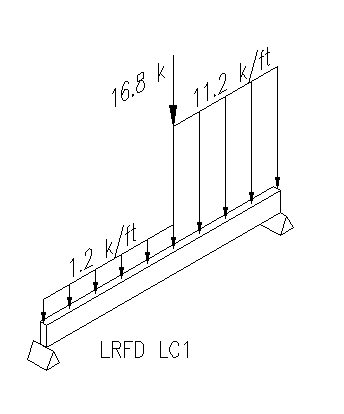
Problem 2.2: Sketch an isometric diagram of the beam in problem 2.1 with the annotated loads for cases LRFD-LC2b, LRFD-LC4b, ASD-LC2, and ASD-LC6a. You will end up with four sketches, each showing the fully loaded beam for one load case (i.e. combine all the appropriate load sources from Figure 2.5.1 for each load case). See Figure 2.5.2 for an example load combination drawing. Digitally include the sketches in your EXCEL file on a page separate from the calculation. Assume that the unit live load is less than 100 psf and that the beams supports neither a garage or place of public assembly.
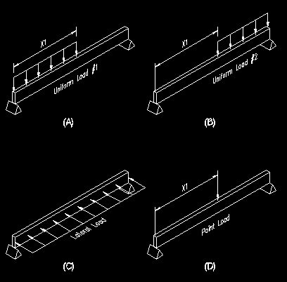
Figure 2.5.1
Load Sources for Sample Data

Table 2.5.1a
Sample Data and Results: ASCE 7-10
| Loads | Identifier | Source 1 | Source 2 | Source 3 | Source 4 | |
| Units | klf | klf | klf | k | ||
| Dead | D | 0.85 | 8 | 0 | 12 | |
| Live | L | 0.55 | 0 | 0 | 10 | |
| Roof Live | Lr | 0 | 0.25 | 0 | 13 | |
| Soil Loads | H | 0 | 0 | 0 | 0 | |
| Snow | S | 0 | 0.85 | 0 | 0 | |
| Rain | R | 0 | 0 | 0 | 0 | |
| Flood | Fa | 0 | 0 | 0 | 0 | |
| Atmospheric Ice | Di | 0 | 0 | 0 | 0 | |
| Wind | W | 0 | 0 | 0.25 | 0 | |
| Wind on Ice | Wi | 0 | 0 | 0 | 0 | |
| Earthquake | E | 0 | 0 | 0.35 | 0 | |
| LRFD | max value | 1.9 | 11.2 | 0.35 | 45.2 | |
| min value | 0.765 | 7.2 | -0.35 | 10.8 | ||
| LRFD-LC1 | 1.19 | 11.2 | 0 | 16.8 | ||
| LRFD-LC2a | 1.9 | 9.725 | 0 | 36.9 | ||
| LRFD-LC2b | 1.9 | 10.025 | 0 | 30.4 | ||
| LRFD-LC2c | 1.9 | 9.6 | 0 | 30.4 | ||
| LRFD-LC2ice | 1.9 | 9.6 | 0 | 30.4 | ||
| LRFD-LC3a | 1.57 | 10 | 0 | 45.2 | ||
| LRFD-LC3b | 1.02 | 10 | 0.125 | 35.2 | ||
| LRFD-LC3c | 1.02 | 10 | -0.125 | 35.2 | ||
| LRFD-LC3d | 1.57 | 10.96 | 0 | 24.4 | ||
| LRFD-LC3e | 1.02 | 10.96 | 0.125 | 14.4 | ||
| LRFD-LC3f | 1.02 | 10.96 | -0.125 | 14.4 | ||
| LRFD-LC3g | 1.57 | 9.6 | 0 | 24.4 | ||
| LRFD-LC3h | 1.02 | 9.6 | 0.125 | 14.4 | ||
| LRFD-LC3i | 1.02 | 9.6 | -0.125 | 14.4 | ||
| LRFD-LC4a | 1.57 | 9.725 | 0.25 | 30.9 | ||
| LRFD-LC4b | 1.57 | 9.725 | -0.25 | 30.9 | ||
| LRFD-LC4c | 1.57 | 10.025 | 0.25 | 24.4 | ||
| LRFD-LC4d | 1.57 | 10.025 | -0.25 | 24.4 | ||
| LRFD-LC4e | 1.57 | 9.6 | 0.25 | 24.4 | ||
| LRFD-LC4f | 1.57 | 9.6 | -0.25 | 24.4 | ||
| LRFD-LC4ice1 | 1.57 | 10.025 | 0 | 24.4 | ||
| LRFD-LC4ice2 | 1.57 | 10.025 | 0 | 24.4 | ||
| LRFD-LC5a | 1.57 | 9.77 | 0.35 | 24.4 | ||
| LRFD-LC5b | 1.57 | 9.77 | -0.35 | 24.4 | ||
| LRFD-LC6a | 0.765 | 7.2 | 0.25 | 10.8 | ||
| LRFD-LC6b | 0.765 | 7.2 | -0.25 | 10.8 | ||
| LRFD-LC6ice1 | 0.765 | 7.2 | 0 | 10.8 | ||
| LRFD-LC6ice2 | 0.765 | 7.2 | 0 | 10.8 | ||
| LRFD-LC7a | 0.765 | 7.2 | 0.35 | 10.8 | ||
| LRFD-LC7b | 0.765 | 7.2 | -0.35 | 10.8 | ||
| ASD | max value | 1.4 | 8.85 | 0.245 | 0 | |
| min value | 0.51 | 4.8 | -0.245 | 0 | ||
| ASD-LC1 | 0.85 | 8 | 0 | 12 | ||
| ASD-LC2 | 1.4 | 8 | 0 | 22 | ||
| ASD-LC2ice | 1.4 | 8 | 0 | 22 | ||
| ASD-LC3a | 0.85 | 8.25 | 0 | 25 | ||
| ASD-LC3b | 0.85 | 8.85 | 0 | 12 | ||
| ASD-LC3c | 0.85 | 8 | 0 | 12 | ||
| ASD-LC3ice1 | 0.85 | 8.85 | 0 | 12 | ||
| ASD-LC3ice2 | 0.85 | 8.85 | 0 | 12 | ||
| ASD-LC4a | 1.2625 | 8.1875 | 0 | 29.25 | ||
| ASD-LC4b | 1.2625 | 8.6375 | 0 | 19.5 | ||
| ASD-LC4c | 1.2625 | 8 | 0 | 19.5 | ||
| ASD-LC5a | 0.85 | 8 | 0.15 | 12 | ||
| ASD-LC5b | 0.85 | 8 | -0.15 | 12 | ||
| ASD-LC5c | 0.85 | 8 | 0.245 | 12 | ||
| ASD-LC5d | 0.85 | 8 | 0.245 | 12 | ||
| ASD-LC6a1 | 1.2625 | 8.1875 | 0.1125 | 29.25 | ||
| ASD-LC6a2 | 1.2625 | 8.1875 | -0.1125 | 29.25 | ||
| ASD-LC6a3 | 1.2625 | 8.6375 | 0.1125 | 19.5 | ||
| ASD-LC6a4 | 1.2625 | 8.6375 | -0.1125 | 19.5 | ||
| ASD-LC6a5 | 1.2625 | 8 | 0.1125 | 19.5 | ||
| ASD-LC6a6 | 1.2625 | 8 | -0.1125 | 19.5 | ||
| ASD-LC6b1 | 1.2625 | 8.6375 | 0.18375 | 19.5 | ||
| ASD-LC6b2 | 1.2625 | 8.6375 | -0.18375 | 19.5 | ||
| ASD-LC7a | 0.51 | 4.8 | 0.15 | 7.2 | ||
| ASD-LC7b | 0.51 | 4.8 | -0.15 | 7.2 | ||
| ASD-LC7ice1 | 0.51 | 4.8 | 0 | 7.2 | ||
| ASD-LC7ice2 | 0.51 | 4.8 | 0 | 7.2 | ||
| ASD-LC8a | 0.51 | 4.8 | 0.245 | 7.2 | ||
| ASD-LC8b | 0.51 | 4.8 | -0.245 | 7.2 |
Figure 2.5.2
Sample Load Combination Drawing

Problem 2.3: A column is found to have the axial capacities shown below. If the loads that are to be applied consist of dead load (1 part), floor live load (2 parts), roof live load (1.5 part), and snow load (2.5 parts), what are the maximum service level magnitudes of each of these load components for each design method?
Which method is the more restrictive in this case?
Hint: Your final Ps,equiv (Ps,equiv = D + L + Lr + S) must ensure that all the load combination results must be less than or equal to the limiting values. In other words, to check your results, feed them back into your spreadsheet. The largest load combination result must be less than or equal to the given limiting values.
Assume that the unit live load is less than 100 psf and that the column supports neither a garage nor place of public assembly.
Solution Table
Service Level Forces
| LRFD | ASD | |
| Capacity | fPn = 510 k | Pn/W = 425 k |
| Dead Load, D | ||
| Floor Live Load, L | ||
| Roof Live Load, Lr | ||
| Snow Load, S |