|
|
Section 5.5
Strength Limit State
Last Revised: 11/04/2014
The only strength based limit states associate with a properly designed (i.e. meets all the applicable limitations) welds are the strength of the weld and the strength of the base metal that the weld is attached to. The computation of these limit states is presented in section J2.4 of the SCM specification.
The Limit State:
As with all strength based limit states in the specification, the limits are expressed as:
| LRFD | ASD |
| Pu < fRn | Pa < Rn/W |
| Req'd Rn = Pu / f < Rn | Req'd Rn = Pa W < Rn |
| Pu / (fRn) < 1.00 | Pa / (Rn/W) < 1.00 |
| f varies. See SCM Table J2.5 | W varies. See SCM Table J2.5 |
The values of Pu and Pa are the LRFD and ASD factored loads, respectively, applied to the bolt. These forces are computed using the mechanics principles discussed in Section 4.3.
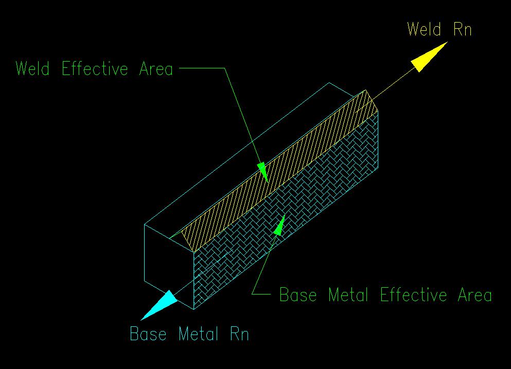
In this case Rn is the nominal shear strength of the weld or base metal.
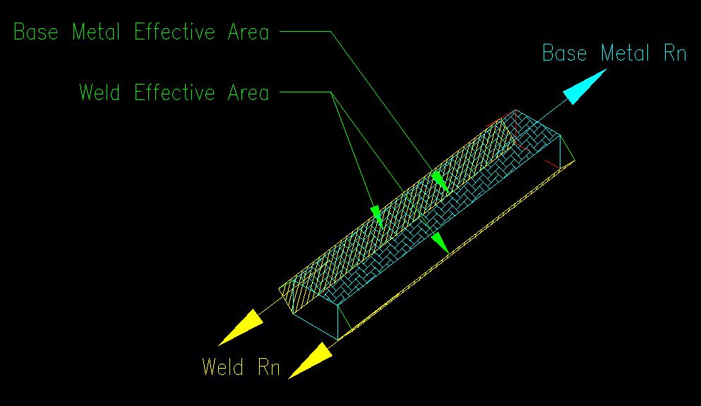
For the limit state related to base metal strength the nominal strength is:
Rn = FBMABM
For the limit state related to weld metal strength the nominal strength is:
Rn = FwAw
The controlling Rn is the one that has the least strength. This leads to the expression:
Rn = min[FBM1ABM1, FBM2ABM2, FwAw]
The definitions of the variables are found in J2.4. The two base metal terms are place there since it is likely that the two pieces being connected will have different capacities. The determination of the effective areas for the weld metal was presented in Section 5.2 of these notes. The determination of the effective areas for the base metal were presented in Section 5.3 of this text.
Since Aw and ABM always have the same lengths, it is common when computing the capacity of the connection, to consider only a unit length of weld to determine the controlling capacity of the welded connection. For example, we might consider only one inch of weld and determine the capacity of the weld and of the base metal, taking the lesser of the two, and continuing on to compute the capacity of the connection.
The values for FBM, Fw, f, and W are obtained from SCM Table J2.5.
Table J2.5 is divided into sections relating to the different types of welds.
For CJP welds, the limit state of weld strength will never control since both the weld and the base metal have the same effective area and the filler material is constrained to be stronger than the base metal. Consequently, only the capacity of the base metal is of concern.
For PJP welds, the effective areas for the weld and base metals differ, with the weld effective area being less than the base metal. If the weld's effective throat is small enough, then the weld strength will control over the base metal strength.
For fillet, plug, and slot welds the forces are all considered to be shearing regardless of force direction relative to the weld. The same assumption can be made about the forces in the base metal. This leads to the following values:
Fw = 0.60 FEXX and FBM = 0.60 Fu
Where FEXX is the ultimate strength of the welding electrode and Fu is the ultimate strength of the base metal.
The Effect of Angle of Load to Axis of a Fillet Weld
As can be seen by the use of the 0.60 coefficient on FEXX, the assumption is that the weld resists the forces using its shear strength. However, if the load direction is not parallel to the axis of the weld then there is a component of the force that causes tension on the effective area as shown in Figure 5.5.1. Since the material is stronger in tension, the use of only the shear strength is conservative. This is normally what is done, however the specification makes provision for the angle of the force to the weld when the force is concentric to weld group and is in the same plane as the weld group.
Figure 5.5.1
Components of Force
Click on image for larger view
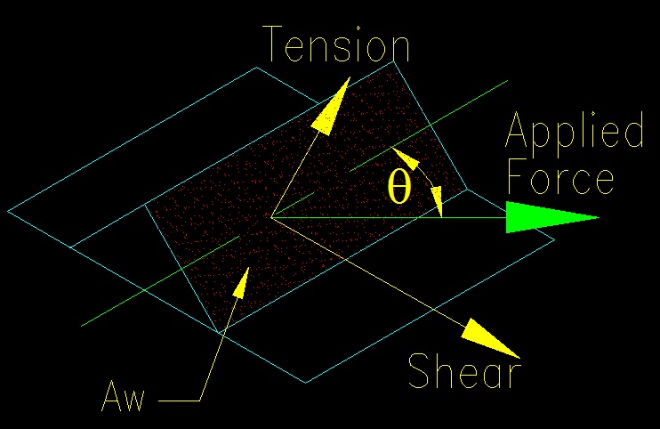
The formula for the increased weld metal material strength is found in SCM J2.4(a). Extracting the FEXX term, the remaining function is the coefficient to FEXX. A value of 0.6 represents pure shear and a value of 1.0 represents pure tension. Since a fillet weld's effective area is not coplanar with the weld group, you never have the case of pure tension in the weld and consequently the coefficient on FEXX will not reach 1.0. Figure 5.5.2 shows the variation of the coefficient with angle between weld axis and force direction.
Figure 5.5.2
FEXX Coefficient with respect to Angle of Load to Weld Axis
This modified weld metal strength can be applied to any qualified segment of the weld. The criteria being:
- The applied force is concentric with the weld group.
- The applied force is in the plane of the faying surface (i.e. the applied force is in the plane of the weld group.
- The weld is a fillet weld.
- The weld group is a "linear weld group" as defined in the user note in SCM J2.4(a).
The condition where the load is eccentric and out of plane of the load group is treated in specification section J2.4(b). We will cover this in Section 5.6 of these notes.
Section J2.4(c) of the specification expands on J2.4(a) and allows you to sum the capacities of the various weld length segments using SCM equation J2-9a (not using the SCM equation J2-5 modifier) to find the capacity of the weld group. Alternately SCM equation J2-9b is provided to approximate the same effect without computing the modified coefficient.
Largest Effective Fillet Weld Size
As previously mentioned in the effective area discussion, there is a point where increasing fillet weld size is ineffective because the base metal strength controls. This can be seen by looking at the strength equations.
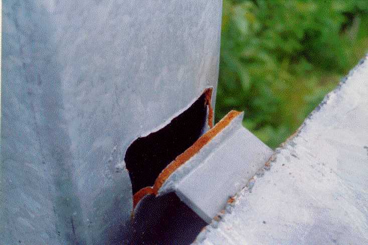
Figure 5.5.3 shows an example where the weld is obviously stronger than the base metal. Adding additional weld to this connection would not have strengthened it. Additional weld would have been a waste of resources.
Figure 5.5.3
Base Metal Failure
Click on image for larger view
Consider the FBD in Figure 5.5.4 of a fractured weld and fractured base metal. This figure is taken from Figure 5.3.3.
Figure 5.5.4
Connection FBD
Click on image for larger view
We will first determine a relationship between weld size and base metal thickness for the condition shown in Figure 5.5.1. In this FBD the base metal force is shared between two equal size fillet welds (one weld on either side of the base metal). The largest effective fillet weld size will be the size where the weld strength equals the base metal strength:
2(0.6FEXX) te L > (0.60Fu) tBM L
After performing the algebra, we get a relationship between weld size and base metal thickness.
te = 0.707 a > 0.5 (Fu / FEXX) tBM
This formula tells us that any weld size larger the quantity shown is no longer contributing to the strength of the connection.
Consider now the case where the strength of the base metal is compared to only one fillet weld as shown in Figure 5.5.5. This FBD is also taken from Figure 5.2.3.
Figure 5.5.5
Connection FBD
Click on image for larger view
In this FBD the base metal force is carried by one fillet weld. The largest effective fillet weld size will be the size where the weld strength equals the base metal strength:
(0.6FEXX) te L > (0.60Fu) tBM L
After performing the algebra, we get a relationship between weld size and base metal thickness.
te = 0.707 a > (Fu / FEXX) tBM
This formula tells us that any weld size larger the quantity shown is no longer contributing to the strength of the connection when only weld support a base metal location.