|
|
Section 6.2
General Member Buckling Concepts
Last Revised: 11/04/2014
To be able to compute the strength of a column, you need to understand general buckling concepts. These concepts are generally taught in a basic mechanics course. This section is intended to be a refresher of the basics as well as an introduction to how these concepts are applied by the SCM.
First, compressive strength is dependent on the direction of assumed buckling. Most compression members have a definite set of principle axis. Buckling will occur ABOUT one of these axes.
Second, the support conditions at either end of the column will influence the compressive strength in each of the principle planes.
Principle Axis and Planes
|
Figure 6.2.1 |
|
|
|
Figure 6.2.2 |
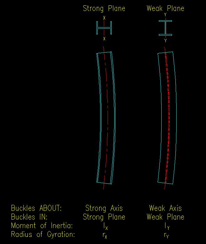 |
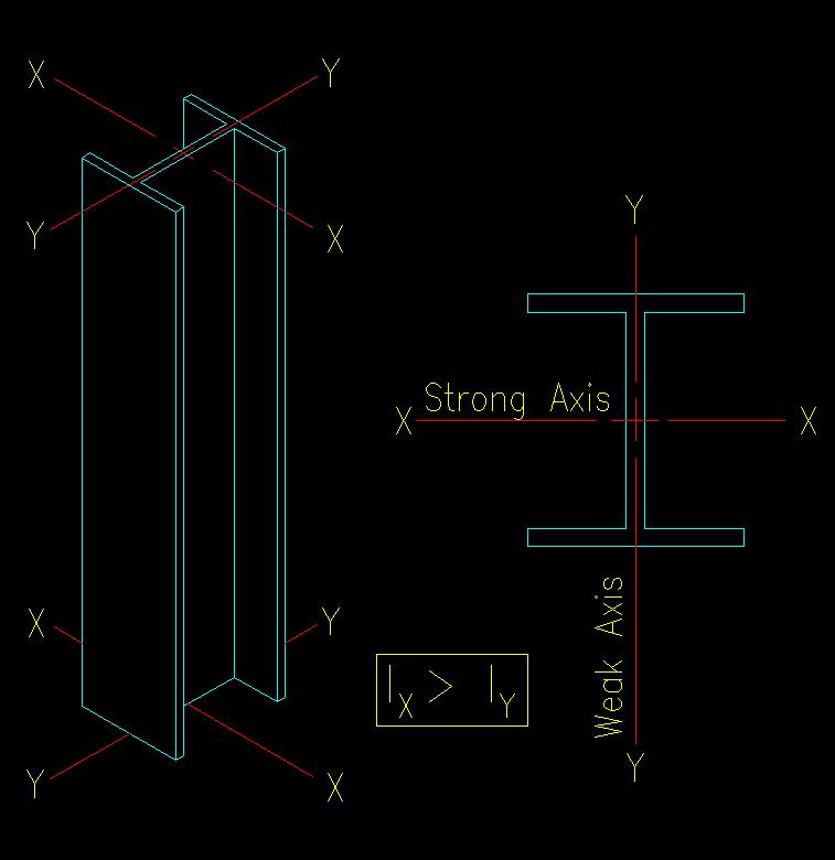
Figure 6.2.1 illustrates the principle axes of a typical wide flange compression member. Other members shapes can be similarly drawn. With the exception of circular (pipe) sections, all the available shapes have a readily identifiable set of principle axes.
Buckling is a two dimensional (planar) event. In other words it happens IN a PLANE that is perpendicular to the AXIS that it happens ABOUT. Figure 6.2.2 shows planar views of the two principle planes for the W section shown in Figure 6.2.1.
Effective Length Coefficients and End Support Conditions
Theoretically, end supports are either pinned or fixed. In reality they can be designed to be pinned or rigid and may actually fall somewhere in between truly pinned or fixed. The support conditions will have an impact on the effective length, Le, of the compression member and can be different in each plane.
In mechanics, you were introduced to effective length coefficients for columns. In review, the effective length, Le, of a compression member is the distance between where inflection points (an inflection point is a location of zero moment) are, or would be, on a compression member. The effective length can be expressed as:
Le = K L
Where K is an effective length coefficient and L is the actual length of the compression member in the plane of buckling.
The standard effective length coefficients are shown in SCM Table C-C2.2 (SCM page 16.1-240).
Three of the cases shown in SCM Table C-C2.2 (a,b, and d) are for cases where there is no lateral translation of the ends relative to each other (i.e. sidesway is inhibited). The other three cases involve lateral movement of the ends relative to each other (i.e. sidesway is uninhibited). In the building industry, the cases with no joint translation are considered to be "braced frames" since some kind of bracing between the two levels is necessary to prevent lateral movement under shearing loads. The other cases are referred to as being "unbraced frames".
Figure 6.2.3 depicts the two types of frames. The brace in the braced frame takes the lateral load P and is axially very stiff resulting in neglectable deformation of the frame. As as result of lack of lateral displacement, the two columns shown see no moment resulting from the lateral load effects. On the other hand, the unbraced frame carries all the lateral load by shear in the columns. There is substantial lateral movement, inducing moment in each of the columns.
|
Figure 6.2.3 |
|
|
|
Figure 6.2.4 |
|
|
Figure 6.2.4 shows that different lengths of the same column can have different effective length coefficients in the same plane of buckling. For example, the column on grid 3 is unbraced on the upper level but is braced on the lower. Note that the brace on the lower level effectively prevents the lower level from moving laterally relative to the foundation level in the plane of the frame, so all columns in the lower level are considered to be braced in the plane of the frame. There are no braces in the upper level so all of those columns are considered to be unbraced in the plane of the frame in that level.
Note that all the columns shown have an out-of-plane direction that must also be considered as well. Each direction will have totally independent lateral support and end conditions. It is highly recommended that you to draw both elevations of the column so that you can clearly see the conditions that apply to each column.
Also note that the columns may have different laterally unsupported lengths in each direction as well.
In Figure 6.2.4 you will notice that the connection of the girders to the columns will also have an effect on the fixity at the end of each column segment.
If the beam to column connection is designed to resist/transfer moment, then the connection is partially fixed. The connecting beams are not perfectly rigid and will allow a little end rotation at the end of the column. This will effect the location of the inflection points. This means that the theoretical effective length coefficients of SCM Table C-C2.2 are not applicable.
If the beam to column connection is not designed specifically to resist/transfer moment, then the connecting beams will not resist rotation of the column segment end and can be considered to be pinned when using SCM Table C-C2.2.
The SCM provides a procedure that considers relative rotational stiffness at either end of a column segment for determining the column's effective length coefficient, K in the plane of the frame. This method starts on SCM page 16.1-239.
Basically, the method computes a "G" factor at each end of the column segment that accounts for the stiffness of all members that contribute to rotational resistance in the plane of the frame at the connection. You only consider members that have moment connections to the joint.
Click on this link to see a power point presentation that illustrates the method: Effective Length Coefficients
Using this method, the effective length for most columns can be determined. Example problem 6.3 shows how the method is applied to columns in a hypothetical frame.
Having the ability to determine effective lengths, we can now determine the strength of a column.