|
|
Section 10.7
The Design Process
The design of a composite beam involves a number of choices. Here, we will discuss the various considerations involved in the selection process and some typical ways that engineers approach the problem.
Design of the Slab
Typically the concrete slab acts as a beam spanning between supporting beams. The slab's span is perpendicular to the span of the supporting beams. The selection of the design variables (thickness and reinforcing) is a solid one-way slab design problem using principles of concrete design. In the United States, this is governed by the provisions of ACI 318 (Reference 14).
For the purposes of designing the composite beams it is essential to know that the wider the spacing of the supporting beams, the thicker the slab. ACI 318 (Reference 14) Table 9.5a suggests the following thicknesses for solid one-way slabs for which deflections are not computed. The thicknesses determined with these ratios tend to be conservative and are a good starting point for design:
| Support/Continuity | Min. Thickness |
| Simply Supported | Span / 20 |
| One End Continuous | Span / 24 |
| Both Ends Continuous | Span / 28 |
| Cantilever | Span / 10 |
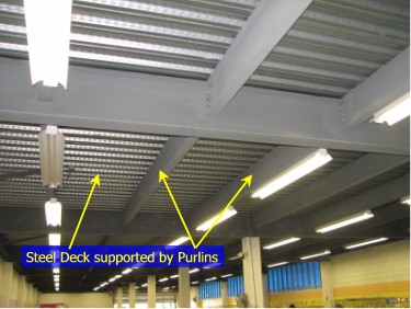
Another option is to use composite steel-concrete decking. The Steel Deck Institute has a number of publications that can help you with selection of an appropriate steel deck/concrete slab combination. Figure 10.7.1 shows the underside of steel decking supported by steel beams. A concrete slab is poured on top of the decking. One significant advantage of steel decking is that the decking eliminates the need for formwork. Shoring may be required until the concrete sets and gains sufficient strength to support its self.
Figure 10.7.1
Steel Decking Supported By Steel Beams
Selecting the Steel Beam
One of the first steps in the design process is to determine the loads supported by the composite beam. In the vast majority of cases, the tributary width is constant and, consequently, the loads are uniform. If the tributary area is not constant, then it is necessary to identify the tributary area supported by the beam and compute the loading diagram for the beam. See A Beginner's Guide to Structural Mechanics/Analysis for more information on how to identify tributary areas and compute beam loadings.
Once the loading diagram for the proposed beam has been defined, structural analysis techniques can be used to identify the shear, moment and deflection diagrams for various load cases that the member will be subjected to.
At this point, a decision must be made concerning shoring.
If the beam is to be unshored during construction, then a steel beam is selected to support the construction loads (including beam weight, formwork, slab weight, and construction live loads). The beam is considered to be laterally unsupported (i.e. Lb = beam span) unless provisions are made in the design to provide lateral support for the beam until the concrete hardens. The beam selection process was covered in BGSCM 8.6.1. The applicable limit states for beam size selection include: shear, flexure and deflection.
If shoring is supplied, then the steel beam selection is not generally influenced by the construction loads as shoring keeps shears, moments, and deflections small until it is removed. The shored member must still be capable of supporting the construction loads, but that is rarely an issue. The composite section must only satisfy the limit states associated with the final, fully composite state. The only sure way to make sure that you get the lightest section that will work, is to sort the available sections by weight then try each in turn, starting from the lightest, then working your way up the list until you find the first one that satisfies all the limit states. The applicable limit states for composite beam size selection include: shear, flexure and deflection.
Selecting the Anchors
The type of anchor to use will depend on what is available. You should consult with the fabricator for your project if there is any question about what is available. Generally, most fabrication shops have access to welded steel headed stud anchors. Studs are generally quicker and cheaper than other types of anchors.
The number and layout of the studs is done as described in Chapter 10.5.