|
Limit State of Flexural Buckling for Compact and Non-compact Sections |
|
|
Section 7.4
Limit State of Flexural Buckling for Slender Sections
Last Revised: 04/19/2021
The flexural buckling strength for slender sections (i.e., those sections that have slender elements as defined by SCM B4) limit state is found in SCM specification E7. SCM Equation E3-2 and E 3-3 are used to compute the critical flexural buckling stress, Fcr, of slender sections. The effect of local buckling is accounted for by the use of a reduced cross-sectional area, Ae.
The main difference between SCM E3 and SCM E7 is that SCM E7 includes effects of both general and local buckling whereas SCM E3 only considers the effects of general bucking.
Note that this section is invoked by few of the standard rolled shapes unless the steel strength, Fy, is unusually high. You can prove this by creating a spreadsheet that computes the compactness criteria for all rolled sections.
The Limit State
The basic limit state follows the standard form. The statement of the limit states and the associated reduction factor and factor of safety are given here:
| LRFD | ASD |
| Pu < fcPn | Pa < Pn/Wc |
| Req'd Pn = Pu / fc < Pn | Req'd Pn = Pu Wc < Pn |
| Pu / (fcPn) < 1.00 | Pa / (Pn/Wc) < 1.00 |
| fc = 0.90 | Wc = 1.67 |
The values of Pu and Pa are the LRFD and ASD factored loads, respectively, applied to the column.
In this case Pn is the nominal compressive strength of the member is computed using SCM equation E7-1:
Pn = FcrAe
Where:
- Fcr is the flexural buckling stress, computed by SCM Equation E3-2 or E3-3, as appropriate.
- Ae is the effective cross-sectional area of the member and equals the summation of the effective areas of the cross-sectional elements.
Computing Ae
SCM E7 has two subsections which are used to compute Ae for Round HSS section (SCM E7.2) and all other sections (SCM E7.1).
Slender Element Members Excluding Round HSS, SCM E7.1
For all sections, except for round HSS, Ae is computed as the sum of the effective areas of each cross-sectional element (bet).
be is computed using the equations presented in SCM E7.1. Equation E7-2 simply says that there is not a reduction for a cross-sectional element that is not slender. Equation E7-3 finds the effective width as a reduction of the actual cross-sectional element width based on the slenderness factor, slenderness limit as defined in SCM Table B4.1a. The formula is also a function of the Fcr and, indirectly, Fy.
SCM Equation E7-3 requires the separate computation of several subterms, including the width-to-thickness ratio for the element, l, the limiting width-to-thickness ratio, lc, and the elastic local buckling stress, Fel. Two coefficients, c1 and c2, are taken from SCM Table E7.1.
It is worth reading the commentary on this section (see SCM pages 16.1-318 through 16.1-321). The method, new in the SCM 15th edition, is based on a concept used for years in the North American Specification for the Design of Cold-Formed Steel Structural Members (AISI 2001, 2007, 2012).
The commentary illustrates that the equations of SCM E7.1 and SCM Table B4.1a can be combined to arrive at a single equation for be, (SCM equation C-E7-13) with a table of coefficients (SCM Table C-E7.1) providing many of the equation's terms based on SCM Table B4.1a case and Table E7.1 case. This is possible because lc is based on formulas in SCM Table B4.1a according to the 8 cases provided for members subject to axial compression. It appears, that SCM equation C-E7-13 is the more useful equation.
It is acknowledged in the commentary that dealing with slender compression elements is an involved process. They point out that the exercise is rarely undertaken with the current rolled shapes and typical steel types.
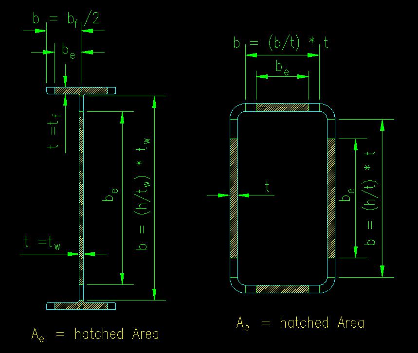
Examples of SCM E7.1 effective areas are shown in Figure 7.4.1. In each of the cases shown, be is computed separately for each of the hatched areas.
For the W section, the web (a stiffened element) has a "width, b" = (h/tw) * tw, where both h/tw and tw are tabulated values. The flanges have four, identical, unstiffened elements have a b = bf/2 and a thickness of t = tf. Ae can be taken as the gross area, Ag, less the area lost using the reduced widths or as a sum of the hatched areas. When be is less than b, the loss in cross-sectional area becomes (b - be)*t. The resulting Ae equals Ag - [ ((b - be)*tw)web + (4*(b-be)*tf)flanges]. A similar computation can be done for the HSS section.
Figure 7.4.1
Ae for Slender Sections
Click on section for larger view
Round HSS
The equation for Ae is much easier to compute for Round HSS. In this case, if the section is slender, then use SCM equation E7-7. SCM equation E7-6 applies to non-slender sections and can be taken as the upper limit of SCM equation E7-7.
Sample Spreadsheet Calculation
The following spreadsheet example computes the nominal capacity of a W section column according to the requirements of SCM Chapter E. The local buckling cases change if you go to other types of compression members. Note that Ae = Ag if no elements are slender, thus making the calculation the same as SCM E3.
| Try | W16x31 | Local Buckling Criteria: SCM B5, E7 | |||||
| Ag | 9.13 | in2 | Unstiffened (flanges) | ||||
| rx | 6.41 | in | Case 1, lr | 13.487 | |||
| ry | 1.17 | in | Case (c), c1 | 0.220 | |||
| bf | 5.53 | in | Case (c), c2 | 1.490 | |||
| bf/2tf | 6.28 | Act/limit | 0.46 | Not Slender | |||
| h/tw | 51.6 | Fel | 511.95 | ||||
| tw | 0.275 | in | b | 2.77 | in | ||
| tf | 0.44 | in | be | 2.77 | in | ||
| Area Reduction | 0.00 | in2 | |||||
| Steel Type | A992 | ||||||
| Fy | 50 | ksi |
Stiffened (web) |
||||
| Case 5, lr | 35.884 | ||||||
| (Lc/r)x | 1.87 | Case (a), c1 | 0.180 | ||||
| (Lc/r)y | 10.26 | Case (a), c2 | 1.310 | ||||
| Controlling | 10.26 | Act/limit | 1.43 | Slender | |||
| Fel | 41.50 | ||||||
| Fe | 2720.86 | ksi | b | 14.19 | in | ||
| Fy/Fe | 0.02 | be | 10.84 | in | |||
| Fcr | 49.62 | ksi | Area Reduction | -0.92 | in2 | ||
| Ae | 8.21 | in2 | |||||
| Strength: | |||||||
| Pn | 407.30 | kips | |||||