BGASCE7-10 Section 6.7.1
Example Problem 6.1
Last Revised: 11/04/2014
Given: The two buildings depicted in Figures 6.7.1 & 6.7.2 and the criteria given for the chapter 6 example problems.
Wanted: Determine the hydrostatic pressure distributions on the structural elements for both buildings plus the total net force on each surface.
Solution: For both problems, the water level is taken at the Basic Flood Elevation (BFE). The solution to the problem is fairly easy as the basic hydrostatic equation is used.
Option 'A' Building
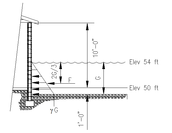
Referring to Figure 6.7.1.1, we can compute the various indicated quantities. The following calculations assume that the building is water tight, or that the flood level rises fast enough that there is a time when the water level in the building is insignificant when the BFE is reached.
Figure 6.7.1.1
Building Option 'A' Quantities

First we compute G by finding the difference between the BFE and the pre-flood ground elevation then adding the erosion and scour allowance:
G = 54' - 50' + 1' = 5'-0"
Once we have G, we can compute the maximum hydrostatic pressure, found at the eroded ground level:
gG = (64.0 pcf) (5 ft) = 320 psf
With this value, we can compute the total force per unit length of wall, F:
F = 0.5 (320 psf)(5 ft) = 800 lb/ft of wall length
The resultant force, F, is center 2/3 down from the flood surface, or 3' 4".
The total force on each wall can now be computed:
On the long walls: Ftotal = (800 lb/ft) (20
ft) = 16.0 kips
On the short walls: Ftotal = (800 lb/ft) (10 ft) = 8.00 kips
Note that these resultant forces are assume to act simultaneously around the building so that the net lateral force on the building is zero in all directions.
An Alternative Look at Option A:
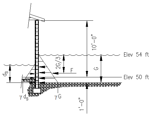
What would the effect be if adequate opening were provided in the walls to allow proper internal flood of the building? In this case, the flood water inside the building does not raise at the same rate as the external flooding so the water level inside the building is taken as the stillwater depth. See Figure 6.7.1.2 for a depiction of the situation.
Figure 6.7.1.2
Building Option 'A' Quantities - Water Inside Alternative

To complete this computation, we need to use ASCE 7-10 equation 5.4-3 to compute the stillwater depth:
ds = 0.65(54' - 49') = 3.25 ft above the eroded ground elevation
If we assume that the soil under the slab does not saturate as fast as the water rises in the structure, we'll conservatively ignore that portion of the internal hydrostatic pressure below the slab surface The maximum internal pressure at the slab elevation is:
depth over slab surface = ds - erosion = 3.25' - 1' = 2.25 ft
maximum internal pressure at slab level = (64.0 pcf) (2.25 ft) = 144 psf
The resulting net force per unit length of wall becomes
Fi = 0.5 (144 psf) (2.25 ft) = 162 lb/ft of wall.
Re-computing the total force on each wall can now be computed:
On the long walls: Ftotal = (800 lb/ft - 162
lb/ft) (20 ft) = 12.8 kips
On the short walls: Ftotal = (800 lb/ft - 162 lb/ft) (10 ft) = 6.38
kips
Comparing with the water tight building assumption, this represents a 20.3% reduction in force.
Option 'B' Building
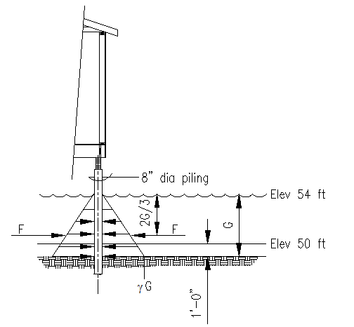
Refer to Figure 6.7.1.3. Notice that some of the required calculations were performed above (i.e. G and gG are the same). Also notice that each piling is completely surrounded by water so that the next force on each pile is zero. This means that there is no strength computation to be performed for the piling for the hydrostatic load case.
Figure 6.7.1.3
Building Option 'B' Quantities

Solution Summary:
Option A:
Option B: