|
|
Section 5.1
Introduction to Welding
Last Revised: 11/04/2014
In the modern world of structural steel, welding is the process of joining two steel pieces (the base metal) together by heating them to the point that molten filler material mixes with the base metal to form one continuous piece. Webster's defines welding as "to unite (metallic parts) by heating and allowing the metals to flow together...". The process of welding is quite complex and the strength of welds is highly dependent on metallurgy, welding procedure, and the skill of the welder.
The welding process has been around for thousands of years.
There are multiple processes and methods for accomplishing this complex task. There are a couple of points to emphasize.
Welding Processes
There are many welding processes, however we will focus on the two most common processes used in structural steel fabrication:
- Shielded Metal Arc Welding (SMAW). A manual process that is typically used when welding in the field. It is also used frequently when welding in a fabrication shop.
- Submerged Arc Welding (SAW). An automated welding process that frequently used when welding in a fabrication shop.
The SMAW process is highly dependent on the skill of the welder while the SAW process is not. The SAW process results in more consistent weld an a strength bonus is given to some welds created with the SAW process.
The materials and the processes used in structural welding are governed by the American Welding Society (AWS) Specification D1.1. This specification is particularly important to welders for determining how to accomplish welds designed by engineers. Engineers need to have some familiarity with the material requirements of the AWS D1.1. The SCM specification is strongly linked to AWS D1.1 and has most of the information that you need to design welds.
Weldability of Metals
Metallurgy has a strong influence on the ability to weld different types of steel. It is important to match weld materials to the base metals that are being connected. The primary reference for matching filler materials to base metals is AWS D1.1 Table 4.4.1. This table gives matching electrode materials for different base metals and the various welding processes. The table is important for engineers when they specify the weld electrodes to be used for the connections that they design. In this basic text, we will use the following electrodes indicated in Table 5.1.1. While this table is basically adequate for most typical projects, for real projects, you should match the requirements of the AWS.
Table 5.1.1
Matching Filler Material for BGSCM Problems
| Base Metal | SMAW | SAW |
| Fy < 50 ksi | E60XX or E70XX | F6XX or F7XX |
| 50 ksi < Fy < 60 ksi | E70XX | F7XX |
| 60 ksi < Fy < 70 ksi | E80XX | F8XX |
Types of Joints
|
Figure 5.1.1 |
 |
There are five basic types of welded joints. The joints are depicted in Figure 5.1.1. They are:
- Butt Joints
- Lap Joints
- Tee Joints
- Corner Joints
- Edge joints
Butt Joints: Butt joints are formed when two plates are butted together. The connection is normally made with a full or partial penetration weld. The edges of the plate are often prepared so that the weld can penetrate deeper into the butt joint. Some times the plates are held apart slightly for the same reason.
Lap Joints: These common joints are made when two members with flat surfaces over lap each other. The connection is normally made with fillet welds along the edges of the connected parts.
Tee Joints: In this type of connection one plate element "T"'s into another. The joint can be made with fillet, partial penetration, or full penetration welds.
Corner Joints: Corner joints are a special type of Tee joint. this connection occurs at the edges of two plates.
Edge joints: This type of connection joins the edges of two plate elements laid together has show in Figure 5.1.1. The connection is made with partial penetration welds. The edges are often times prepared with grooves so that the weld can penetrate deeper.
Types of Welds
The basic weld types are groove welds, fillet welds, and slot & plug welds.
Groove Welds
Groove welds are generally used to fill the gap between the two pieces being connected. They are called groove welds because the edges of the materials being joined are prepared so that there is a groove of some shape formed when the pieces are first laid together. The weld metal fills the groove.
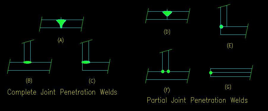
Groove welds are considered to be either "complete joint penetration" (CJP) or "partial joint penetration" (PJP).
A CJP weld completely fills the gap between the two pieces. Parts A, B, and C of Figure 5.1.2 illustrate CJP welds. CJP welds made with appropriate filler material are stronger than the base metals that they connect, so strength calculations are not necessary.
A PJP weld only fills a portion of the gap as seen in Figure 5.1.2 parts D, E, F, and G. PJP welds are used when it is not required to develop the full strength of the connected parts to transfer the load.
Figure 5.1.2
Groove Weld Examples
Click on image for larger view
Fillet Welds
Fillet welds do not penetrate the gap between the parts being connected. A fillet weld generally has a triangular cross section with one leg of the triangle being attached to each piece being connected.
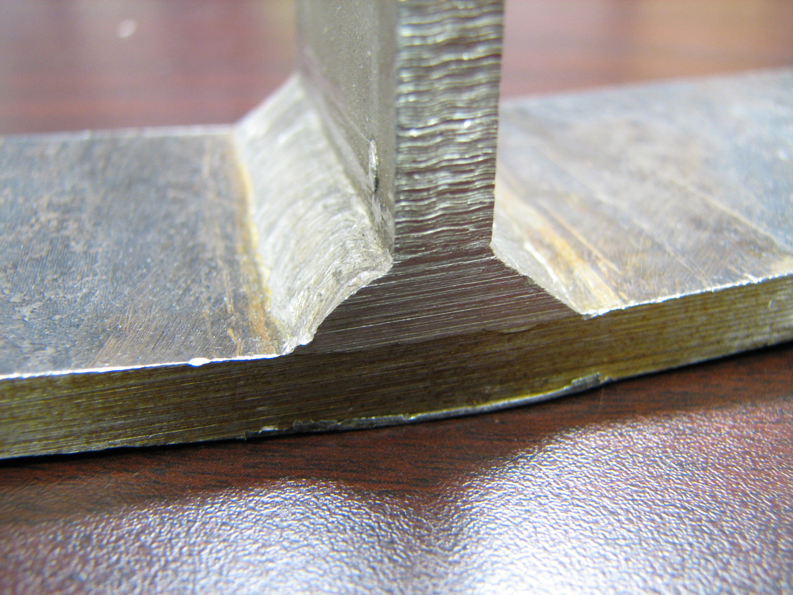
Fillet welds are very common and are used for a variety of connections. A typical fillet weld is shown in Figure 5.1.3.
Figure 5.1.3
Typical Fillet Welded T Joint
Click on image for larger view
Slot & Plug Welds
Slot & Plug welds are similar to fillet welds in that they do not penetrate the gap between the parts being connected. These welds fill a slot or hole in one of the pieces being connected with the connection being between the edge of the slot or hole on the one piece and the surface of the other piece. The welds can be made in conjunction with fillet welds to shorten the lap of two pieces where space is limited.
Prequalified Welded Joints
The AWS specification defines a number of "prequalified" joints that can be made. Before a welded joint can be made on a project, it must be proven that the weld can be made using the desired materials and attain the required strength and ductility. Once the joint has been proven, a welding procedure that details how the weld is to be made is published and the procedure is considered to be prequalified. If the engineer specifies a joint or weld that has not been prequalified it is necessary for the welders to go through the qualification process to develop a new qualified welding procedure.
Before a welder is allowed to make a particular joint he/she must be CERTIFIED to make that weld. The certification process requires the welder to create the weld on a sample using the materials, procedure, and position that will be used for making the final connection. The sample is tested to insure that it meets specifications. Once a welder demonstrates that they can consistently create a weld that meets performance specifications then they are certified to make that particular weld.
The SCM Table 8-2 (SCM pages 8-34 through 8-64) presents that design parameters for the most common prequalified welds used for structural building connections.
Weld Symbols
A means for communicating the intent of the designer to the welder through standard weld symbols has been developed by the AWS. A table defining the weld symbols for prequalified welded joints is included in the SCM on page 8-35. You should take some time to examine this table. Pay particular notice to the notes at the bottom of the table. As an engineer you need to understand the language of the symbols or you may not get the weld that you are expecting.
Some things to notice:
- The basic weld symbol consists of an arrow that points to the faying
surface (i.e. the surface of contact between the pieces being connected) of
the weld and a horizontal line where symbols are placed to describe the type
of weld to be made.
- Figure 5.1.4 shows an example a common mistake. The left example is from a drawing where the designer desired four welds on the outer side of the HSS section, but actually specified the welds as shown. The appropriate symbol is shown on the right side of the figure.
- The arrow may be placed at either end of the horizontal line and may have one or two corners in the leader. The line segments are always straight lines.
- The "field weld" flag and "weld all around" symbols always appear at the
intersection of the horizontal line and the arrow leader.
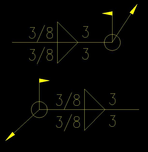
- The flag of the "field weld" always point towards the tail end of the horizontal line as shown in Figure 5.1.5.
- The basic symbols are graphically similar to the type of weld or edge
preparation that needs to be made.
- Figure 5.1.5 illustrates this concept. Notice that the fillet weld symbol has it's "back" (i.e. the vertical line) on the left side of the triangle regardless of which side the arrow is on. The weld information is the same on both weld symbols.
- The arrangement of the symbols and notes on the horizontal line are exactly as shown regardless of which end of the horizontal line the indicating arrow is located.
Figure 5.1.4
Arrow Side / Other Side Example
Click on image for larger view
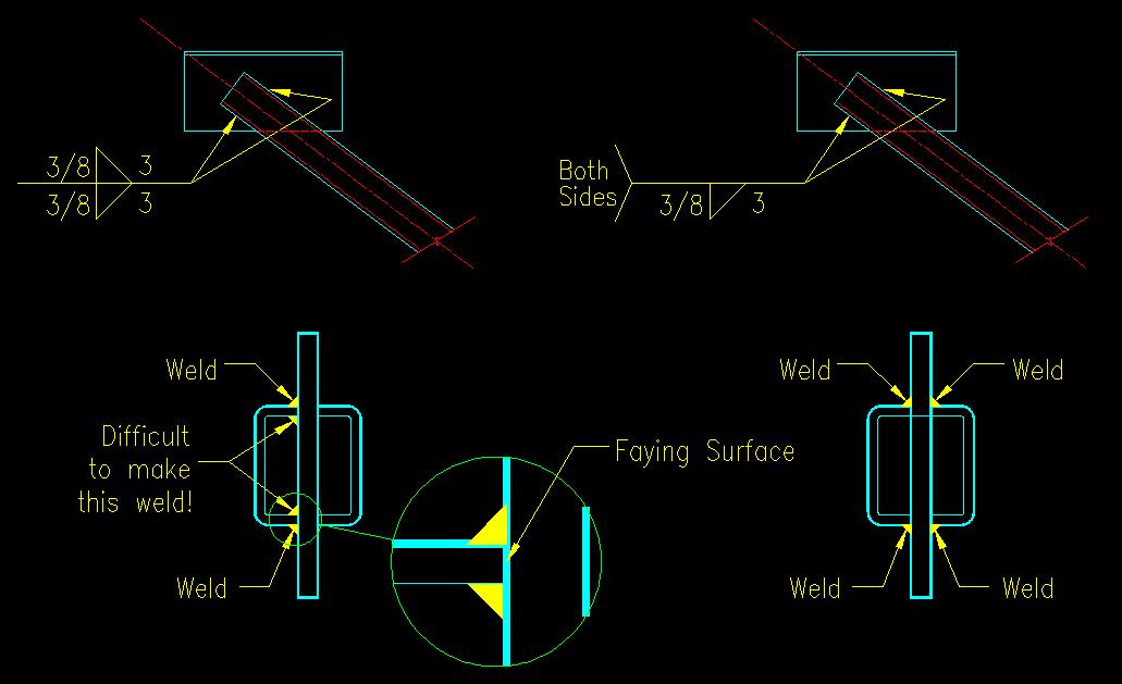
Figure 5.1.5
Weld Information Location
Click on image for larger view
Prequalified Welded Joint Tables
Each AWS standard prequalified joint has a table associated with it. A set of these tables is found in SCM Table 8-2 (SCM pages 8-34 through 8-64). The table gives the geometrical and material parameters associated with the joint. Typically a figure is given to define the different dimensional quantities. The associated table gives the acceptable parameters associated with each dimensional quantity. The table also assigns a joint designation to each weld for each process. This designation directs the welder to the AWS welding procedure associated with the weld.
Weld Quality
As a design engineer you should be aware of the factors affecting weld quality, however it is not the responsibility of the designer to check the quality of the welds.
There are quite a number of factors affecting the quality of a weld. A good quality control program will have procedures in place to ensure that welds are of appropriate quality. The elements of that program will include the use of prequalified welding procedures, performed by welders that have been certified to perform the designated weld, qualified welding inspectors present on the job, and the specification of specialized weld inspection techniques as required.
Some of the factors affecting weld quality are:
- Proper Electrodes, Welding Apparatus, and Procedures
- Proper Edge Preparation
- Control of Distortion
Inspection of welds must be done by qualified individuals. Most engineers are not qualified to determine the quality of weld. Visual inspection is the least expensive method but cannot detect many weld defects. Visual inspection can be used to ensure proper weld size has been obtained. Ultrasonic or X-ray techniques can detect hidden defects of welds but are very expensive. Many projects will specify that these techniques be used to spot check the welding on a certain percentage of the welds and on all welds that are deemed to be particularly critical. There is a good discussion of inspection techniques starting on SCM pg 8-4.
Possible defects in welds include:
- Incomplete Fusion
- Inadequate Joint Penetration
- Porosity
- Undercutting
- Slag Inclusion
- Cracks
Limit States
The primary objective of checking all strength based limit states to ensure that the strength of the structural element is strong enough to handle anticipated forces exerted on them. In the case of welds, this can be expressed as:
The FORCE on the weld < min[STRENGTH of the weld, STRENGTH of adjacent base metal]
For welds, the forces can be resolved into to tension and shear components. In the special case of fillet welds, all stresses are assumed to be shear.
Figure 5.1.6 summarizes the following discussion about determining the forces on welds and the strength of welds.
Force on the Weld
|
Figure 5.1.6 |
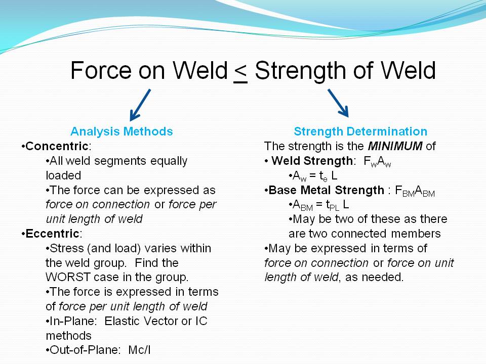 |
The force on any given weld is the result of the forces being applied to the connection and the geometry of the connection. Principles of Mechanics and Structural Analysis are used to determine the force at any particular point in a weld in a connection. The next section discusses several commonly used methods for computing the forces in welds.
Strength of a Weld
Welds have one tensile limit state and one shear limit state. Typically the SCM denotes the nominal capacities of each as Rn.
Tensile Limit State: Tensile Rupture
For the case of tension, the limit state is:
The TENSILE FORCE on the weld < The TENSILE RUPTURE STRENGTH of the weld
Shear Limit States: Shear Rupture
For the case of shear the limit states can be stated as:
The SHEAR FORCE on the weld < The SHEAR RUPTURE STRENGTH of the weld
Strength of Base Metal
The connected parts are referred to as the "base metal". There are two base metal components associated with each weld. The strength of both base metals in the vicinity of the weld needs to be considered. The base metal with the least strength controls the base metal capacity. Typically the SCM denotes the nominal capacities of each as Rn.
Tensile Limit State: Tensile Rupture
For the case of tension, the limit state is:
The TENSILE FORCE on the base metal < The TENSILE RUPTURE STRENGTH of the base metal
Shear Limit States: Shear Rupture
For the case of shear the limit states can be stated as:
The SHEAR FORCE on the base metal < The SHEAR RUPTURE STRENGTH of the base metal