|
Limit State of Flexural Buckling for Compact and Non-compact Sections |
|
|
Section 7.4
Limit State of Flexural Buckling for Slender Sections
Last Revised: 11/04/2014
The flexural buckling strength for slender sections (i.e. those sections that have slender elements as defined by SCM B4) limit state is found in SCM specification E7. The equations used for slender sections are the same as those used in SCM specification E3 with the addition of the term Q. Q is a term that accounts for local buckling effects on overall column strength. When looking at the equations, note that when Q=1 (which is true for non-slender sections) that the equations are the same as the equations in SCM E3.
The advantage of SCM E7 is that this section includes effects of both general and local buckling whereas SCM E3 only considers the effects of general bucking.
Note that this section is invoked by few of the standard rolled shapes unless the steel strength, Fy, is unusually high. You can prove this by creating a spreadsheet that computes the compactness criteria for all rolled sections.
The Limit State
The basic limit state follows the standard form. The statement of the limit states and the associated reduction factor and factor of safety are given here:
| LRFD | ASD |
| Pu < fcPn | Pa < Pn/Wc |
| Req'd Pn = Pu / fc < Pn | Req'd Pn = Pu Wc < Pn |
| Pu / (fcPn) < 1.00 | Pa / (Pn/Wc) < 1.00 |
| fc = 0.90 | Wc = 1.67 |
The values of Pu and Pa are the LRFD and ASD factored loads, respectively, applied to the column.
In this case Pn is the nominal compressive strength of the member is computed using SCM equation E3-1:
Pn = FcrAg
Where:
- Fcr is the flexural buckling stress.
- Ag is the gross cross sectional area of the member.
The SCM has two formulas for determining the flexural buckling stress. The first equation, E7-2, covers both the plastic and inelastic buckling regions of the typical buckling strength curve. as shown in Figure 6.1.3. The second equation, E7-3, covers compression members that are slender.
The criteria for selecting which formula to use is based on either the slenderness ratio for the member or the relationship between the Euler buckling stress and the yield stress of the material. The selection can be stated as:
if (KL/r < 4.71*sqrt(E/QFy)) or (QFy / Fe < 2.25) then
use SCM Equation E7-2
else
use SCM Equation E7-3
The effective length coefficient, K is taken as 1.00 for all purposes of this section if the demand side of the inequality (i.e. Pu or Pa) was determined using the Direct Analysis method, otherwise use the K computed using methods in SCM Appendix 7.
Figure 7.4.1 shows a graph of the Fcr equations for various values of Q.
Figure 7.4.1
Fcr for Slender Sections
Click on image for larger view
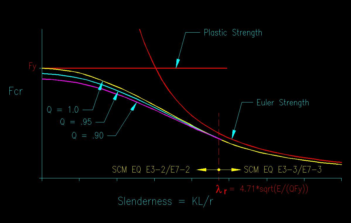
The term Q is a reduction factor that is a function of cross sectional element slenderness and is the product of the reduction factors Qs and Qa.
Qs is a reduction factor for unstiffened cross sectional elements. This factor is a function of the largest width/thickness (b/t) ratio of the unstiffened elements in the cross section. It is computed differently based on the compactness of the section. SCM E7.1 gives, for different types of sections, the limiting b/t ratios for the plastic, inelastic, and elastic buckling ranges and the equations for determining Qs for each region. So, for a given b/t ratio, you can determine which range the element is in and the equation to use for computing Qs.
Qa is a reduction factor for stiffened cross sectional elements. SCM E7.2 takes a different approach to computing Qa than was used for Qs. Qa is taken as a ratio of effective area, Ae, of the member to its actual area, Ag. As this is a buckling problem, we expect to see equations for the three regions, and this section does not disappoint.
Computing Ae
Ae is computed as the sum of the effective areas of each stiffened cross sectional element (bet) and the full area of any unstiffened cross sectional elements. be is computed using the equations presented in SCM E7.2 based on the type of section being considered.
For example in a W cross section section, the stiffened cross sectional element is the web. The web has a "width, b" = (h/tw) * tw., where both h/tw and tw are tabulated values. The effective width, be, is found with SCM equation E7-17. The effective width, be will always be taken as less than or equal to width b. Ae is the gross area, Ag, less the area lost using the reduced web plate width. When be is less than b, the loss in cross sectional area becomes (b - be)*tw. The resulting Ae equals Ag - (b - be)*tw.
From a buckling perspective, the critical buckling stress is achieved when either local buckling capacity or general buckling capacity is reached. If a slender section is part of a slender member then, as the general slenderness parameter (KL/r) increases, there is a point where general buckling will occur before local buckling will occur. If this happens, then local buckling is a moot point and there is no need to adjust the member capacity for the effects of local buckling. The SCM equations in E7.2a do this. The equations are a function of the general buckling critical stress which is a function of general slenderness (KL/r). The result is that there are many times when a section has slender cross sectional elements, but there is no reduction in capacity as a result and Qs=1. In other words, cross sectional element slenderness does not always impact member capacity.
For "box" sections, you typically have two slender elements at a time. This means that you have two cross sectional elements that are losing area. Both need to be accounted for in your Ae calculation.
Figure 7.4.2 illustrates Ae on a W section and rectangular HSS.
Figure 7.4.2
Ae for Slender Sections
Click on section for larger view
Note the gray box on SCM page 16.1-43 that allows you to use Fy for f when using SCM E7.2b. This makes the computation much easier, is slightly conservative, and in few cases does the extra amount make a significant difference.
Sample Spreadsheet Calculation
The following spreadsheet example computes the nominal capacity of a W section column according to the requirements of SCM E7. The local buckling cases and computation of Qs and Qa change if you go to other types of compression members.
| Try | W12X30 | ||
| Ag | 8.79 | in2 | |
| rx | 5.21 | in | |
| ry | 1.52 | in | |
| bf/2tf | 7.41 | ||
| h/tw | 41.8 | ||
| tw | 0.26 | in | |
| Steel Type | A992 | ||
| Fy | 50 | ksi | |
| (KL/r)x | 6.91 | ||
| (KL/r)y | 23.68 | ||
| Controlling | 23.68 | ||
| Local Buckling Criteria: SCM B5, E7 | |||
| Unstiffened | |||
| Case 1, lp | 13.487 | ||
| Act/limit | 0.55 | Not Slender | |
| Qs | 1 | ||
| Stiffened | |||
| Case 5, lp | 35.884 | ||
| Act/limit | 1.16 | Slender | |
| Fe | 510.25 | ksi | |
| Fy/Fe | 0.098 | ||
| f | 47.99 | ksi <-- SCM E7.2a | |
| 1.49sqrt(.. | 36.63 | ||
| b | 10.87 | in | |
| be | 9.82 | in | |
| Ae | 8.52 | in2 | |
| Qa | 0.969 | ||
| Q | 0.969 | ||
| QFy | 48.4 | ksi | |
| Slenderness: | |||
| limit | 300 | ||
| Act/Limit | 0.08 | OK | |
| Compressive Strength: SCM E7 | |||
| Fe | 510.25 | ksi | |
| QFy/Fe | 0.09 | ||
| Fcr | 46.50 | ksi | |
| Pn | 408.73 | kips | |